
【UVM学习笔记】UVM基础—一文告诉你UVM的组成部分
一、Driver驱动器
这段代码是用 SystemVerilog 编写的一个基于 UVM(Universal Verification Methodology)的驱动器(driver)组件,名为 my_driver。它继承自 uvm_driver 类,用于在验证环境中驱动 DUT(Design Under Test,被测设计)的输入信号。下面我将逐步解释这段代码的结构和功能。
1.1 整体结构
代码分为两个主要部分:
- 类定义部分:定义了 my_driver 类,包括构造函数和一个外部声明的任务(main_phase)。
- 任务实现部分:实现了 main_phase 任务,负责具体的信号驱动逻辑。
此外,代码使用 ifndef 和 define 宏来防止重复包含。
1.2 详细解释
1.2.1 宏定义保护
1 | ifndef MY_DRIVER__SV |
检查是否已经定义了宏MY_DRIVER__SV。如果没有定义,则编译器会继续处理后面的代码。
最后,文件末尾的 endif 与开头的 ifndef 配对,结束条件编译块。
1.2.2 类定义
1 | class my_driver extends uvm_driver; |
class my_driver extends uvm_driver:定义一个名为 my_driver 的类,并且表示 my_driver 继承自 UVM 提供的基类 uvm_driver。
uvm_driver 是 UVM 框架中的一个标准组件类,用于将事务级数据转换为 DUT 的引脚级信号。
事务级数据是指更高层次的抽象数据,通常以结构体或类的形式表示,而不是直接的硬件信号(0 和 1)。它描述的是“做什么”,而不是“怎么做”。
假设事务是一个 8 位数据 8’b10100101。
驱动器将其转换为:
top_tb.rxd <= 8’b10100101;(数据信号)
top_tb.rx_dv <= 1’b1;(有效信号)
并在 @(posedge top_tb.clk) 时更新这些信号。
function new:定义类的构造函数,用于创建 my_driver 对象。super.new(name, parent):调用父类 uvm_driver 的构造函数,将 name 和 parent 参数传递给它。这是 UVM 中面向对象编程的标准做法,确保父类的初始化逻辑被执行。extern:表示 main_phase 任务的实现不在类定义内部,而是在外部单独定义。virtual:声明这是一个虚任务,允许子类重写(override)它。这是 UVM 中 phase 方法的常见做法。task main_phase(uvm_phase phase):定义一个名为 main_phase 的任务,接收一个 uvm_phase 类型的参数 phase,表示 UVM 的仿真阶段(这里是 main_phase,通常用于主要的测试执行阶段)。
1.2.3 任务实现
1 | task my_driver::main_phase(uvm_phase phase); |
my_driver::main_phase:明确指定这个任务是 my_driver 类的一部分。
这是 main_phase 的具体实现,负责驱动 DUT 的信号。
uvm_info(“my_driver”, “data is drived”, UVM_LOW):
UVM 提供的日志记录宏,打印信息。my_driver:消息来源(组件名)。data is drived:消息内容。UVM_LOW:日志级别,表示低详细程度。
作用:在 256 个时钟周期内,连续向 DUT 的 rxd 输入随机数据,并将 rx_dv 置为 1,同时记录日志。
所谓类的定义,就是用编辑器写下:
2
3
>...
>endclass
而所谓类的实例化指的是通过new创造出A的一个实例:
2
>a_list = new();
1.2.4 factory机制
factory机制的实现被集成在了一个宏中:uvm_component_utils。这个宏所做的事情非常多,其中之一就是将my_driver登记在UVM内部的一张表中,这张表是 factory 功能实现的基础。只要在定义一个新的类时使用这个宏,就相当于把这个类注册到了这张表中。1
`uvm_component_utils(my_driver)
在给driver中加入factory机制后,还需要对top_tb做一些改动:1
2
3initial begin
run_test("my_driver");
end
但是输出的结果只有两个,没有执行后面的代码,关于这个问题,牵涉UVM的objection机制。1
2
3UVM_INFO my_driver.sv(8) @ 0: uvm_test_top [my_driver] new is called
UVM_INFO @ 0: reporter [RNTST] Running test my_driver...
UVM_INFO my_driver.sv(14) @ 0: uvm_test_top [my_driver] main_phase is called
1.2.4 objection机制
UVM中通过objection机制来控制验证平台的关闭。细心的读者可能发现,在上节的例子中,并没有如2.2.1节所示显式地调用 finish 语句来结束仿真。但是在运行上节例子时,仿真平台确实关闭了。在每个phase中,UVM会检查是否有objection被提起 (raise_objection),如果有,那么等待这个objection被撤销(drop_objection)后停止仿真;如果没有,则马上结束当前 phase。1
2
3
4
5task my_driver::main_phase(uvm_phase phase);
phase.raise_objection(this);
...
phase.drop_objection(this);
endtask
raise_objection语句必须在main_phase中第一个消耗仿真时间的语句之前。
1.2.5 加入virtual interface
使用该方法能够杜绝因为绝对路径所带来的不便,在SystemVerilog中使用interface来连接验证平台与DUT的端口,该端口可以认为是一种总线。
定义interface的方法如下:1
2
3
4
5
6
7
8
9`ifndef MY_IF__SV
`define MY_IF__SV
interface my_if(input clk, input rst_n);
logic [7:0] data;
logic valid;
endinterface
`endif
因为my_driver是一个类,在类中不能使用声明的方法定义一个 interface,只有在类似top_tb这样的模块(module)中才可以。在类中使用的是virtual interface:1
virtual my_if vif;
因此在 中就可以使用该方法来使用:1
2
3
4
5
6
7
8
9
10
11
12
13
14
15
16
17task my_driver::main_phase(uvm_phase phase);
phase.raise_objection(this);
`uvm_info("my_driver", "main_phase is called", UVM_LOW);
vif.data <= 8'b0;
vif.valid <= 1'b0;
while(!vif.rst_n)
@(posedge vif.clk);
for(int i = 0; i < 256; i++)begin
@(posedge vif.clk);
vif.data <= $urandom_range(0, 255);
vif.valid <= 1'b1;
`uvm_info("my_driver", "data is drived", UVM_LOW);
end
@(posedge vif.clk);
vif.valid <= 1'b0;
phase.drop_objection(this);
endtask
下面的问题是,如何把top_tb中的input_if和my_driver中的vif对应起来。
针对该问题,UVM引进了config_db机制。在config_db机制中,分为set和get两步操作。set就是读取数据,get就是输出数据。在top_tb中的代码如下所示:1
2
3initial begin
uvm_config_db#(virtual my_if)::set(null, "uvm_test_top", "vif", input_if);
end
在my_driver中的代码如下所示:1
2
3
4
5
6virtual function void build_phase(uvm_phase phase);
super.build_phase(phase);
`uvm_info("my_driver", "build_phase is called", UVM_LOW);
if(!uvm_config_db#(virtual my_if)::get(this, "", "vif", vif))
`uvm_fatal("my_driver", "virtual interface must be set for vif!!!")
endfunction
首先build_phase也是内置函数,build_phase在new函数之后main_phase之前执行。其中的super.build_phase语句是因为在其父类的build_phase中执行了一些必要的操作。
其中还出现了uvm_fatal宏,其与uvm_info的作用类似。uvm_fatal的出现表示验证平台出现了重大问题而无法继续下去,必须停止仿真并做相应的检查。
config_db的set和get函数都有四个参数,这两个函数的第三个参数必须完全一致。
- set函数的第四个参数表示要将哪个interface通过config_db传递给my_driver
- get函数的第四个参数表示把得到的interface传递给哪个my_driver的成员变量。
set函数的第二个参数表示的是路径索引,UVM通过run_test语句创建一个名字为uvm_test_top的实例,因此需要输入uvm_test_top。无论传递给run_test的参数是什么,创建的实例的名字都为uvm_test_top。其他两个参数以后再说。
set函数与get函数使用双冒号是因为这两个函数都是静态函数,而前面的#键是要传递的类型,这里是virtual my_if。
二、transaction组件
transaction就是一个提供数据传输的打包操作。在不同的验证平台中,会有不同的transaction。一个简单的transaction的定义如下:1
2
3
4
5
6
7
8
9
10
11
12
13
14
15
16
17
18
19
20
21
22
23
24
25
26
27
28
29
30
31`ifndef MY_TRANSACTION__SV
`define MY_TRANSACTION__SV
class my_transaction extends uvm_sequence_item;
rand bit[47:0] dmac;
rand bit[47:0] smac;
rand bit[15:0] ether_type;
rand byte pload[];
rand bit[31:0] crc;
constraint pload_cons{
pload.size >= 46;
pload.size <= 1500;
}
function bit[31:0] calc_crc();
return 32'h0;
endfunction
function void post_randomize();
crc = calc_crc;
endfunction
`uvm_object_utils(my_transaction)
function new(string name = "my_transaction");
super.new();
endfunction
endclass
`endif
其中dmac和smac模拟的就是发送地址和接受地址,ether_type是以太网类型,pload是其携带数据的大小。下面的函数是用于约束上述数据的。通过pload_cons约束将其大小被限制在46~1500byte,CRC暂且使用post_randomize中加的一个空函数calc_crc来对其定义,有兴趣的读者可以将其补充完整。
post_randomize是SystemVerilog中提供的一个函数,当某个类的实例的randomize函数被调用后,post_randomize会紧随其后无条件地被调用。
在transaction定义中,有两点值得引起注意:
- my_transaction的基类是uvm_sequence_item。
在UVM中,所有的transaction都要从uvm_sequence_item派生 - 是这里没有使用uvm_component_utils宏来实现factory机制,而是使用了uvm_object_utils。
下面便是使用transaction的my_driver代码:1
2
3
4
5
6
7
8
9
10
11
12
13
14
15
16
17
18
19
20
21
22
23
24
25
26
27
28
29
30
31
32
33
34
35
36
37
38
39
40
41
42
43
44task my_driver::main_phase(uvm_phase phase);
my_transaction tr;
phase.raise_objection(this);
vif.data <= 8'b0;
vif.valid <= 1'b0;
while(!vif.rst_n)
@(posedge vif.clk);
for(int i = 0; i < 2; i++) begin
tr = new("tr");
assert(tr.randomize() with {pload.size == 200;});
drive_one_pkt(tr);
end
repeat(5) @(posedge vif.clk);
phase.drop_objection(this);
endtask
task my_driver::drive_one_pkt(my_transaction tr);
bit [47:0] tmp_data;
bit [7:0] data_q[$];
//push dmac to data_q
tmp_data = tr.dmac;
for(int i = 0; i < 6; i++) begin
data_q.push_back(tmp_data[7:0]);
tmp_data = (tmp_data >> 8);
end
//push smac to data_q
//push ether_type to data_q
//push payload to data_q
//push crc to data_q
`uvm_info("my_driver", "begin to drive one pkt", UVM_LOW);
repeat(3) @(posedge vif.clk);
while(data_q.size() > 0) begin
@(posedge vif.clk);
vif.valid <= 1'b1;
vif.data <= data_q.pop_front();
end
@(posedge vif.clk);
vif.valid <= 1'b0;
`uvm_info("my_driver", "end drive one pkt", UVM_LOW);
endtask
在main_phase中,先使用randomize将tr随机化,之后通过drive_one_pkt任务将tr的内容驱动到DUT的端口上。
在drive_one_pkt中,先将tr中所有的数据压入队列data_q中,之后再将data_q中所有的数据弹出输入到DUT端口上。
三、env组件
为了能够更好的实例化my_dirver等组件,需要有一个容器去把他们装在一起,这个容器就是env,代码如下:1
2
3
4
5
6
7
8
9
10
11
12
13
14
15
16
17
18
19`ifndef MY_ENV__SV
`define MY_ENV__SV
class my_env extends uvm_env;
my_driver drv;
function new(string name = "my_env", uvm_component parent);
super.new(name, parent);
endfunction
virtual function void build_phase(uvm_phase phase);
super.build_phase(phase);
drv = my_driver::type_id::create("drv", this);
endfunction
`uvm_component_utils(my_env)
endclass
`endif
在my_env的定义中,使用了区别于new的方式,只有使用这种方式实例化的实例,验证平台中的组件在实例化时都应该使用type_name::type_id::create的方式。
回顾一下my_driver的new函数:1
2
3function new(string name = "my_driver", uvm_component parent = null);
super.new(name, parent);
endfuncti
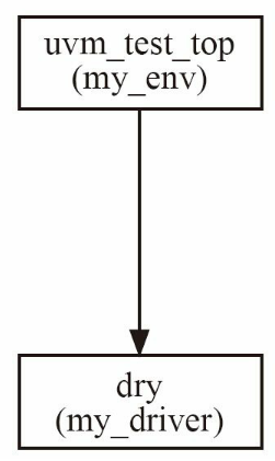
可以看出 my_driver 的父结点就是my_env。通过parent的形式,UVM建立起了树形的组织结构。在这种树形的组织结构中,由run_test创建的实例是树根,并且树根的名字是固定的为uvm_test_top,长出枝叶的过程需要在my_env的build_phase中手动实现。
无论是树根还是树叶,都必须由 uvm_component 或者其派生类继承而来。整棵UVM树的结构如图所示。
1 | initial begin |
1 | `ifndef MY_MONITOR__SV |
1 | virtual function void build_phase(uvm_phase phase); |
五、agent组件
因为my_monitor和my_dirver有相似性,因此可以将两者封装在一起,使用agent组件,代码如下:1
2
3
4
5
6
7
8
9
10
11
12
13
14
15
16
17
18
19
20
21
22
23
24
25
26
27
28
29`ifndef MY_AGENT__SV
`define MY_AGENT__SV
class my_agent extends uvm_agent ;
my_driver drv;
my_monitor mon;
function new(string name, uvm_component parent);
super.new(name, parent);
endfunction
extern virtual function void build_phase(uvm_phase phase);
extern virtual function void connect_phase(uvm_phase phase);
`uvm_component_utils(my_agent)
endclass
function void my_agent::build_phase(uvm_phase phase);
super.build_phase(phase);
if (is_active == UVM_ACTIVE) begin
drv = my_driver::type_id::create("drv", this);
end
mon = my_monitor::type_id::create("mon", this);
endfunction
function void my_agent::connect_phase(uvm_phase phase);
super.connect_phase(phase);
endfunction
`endif
这里有一点比较疑惑,为什么build_phase和connect_phase要在外面定义?为什么不在里面?
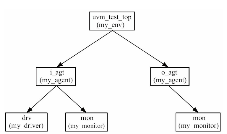
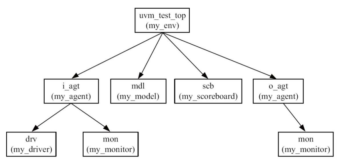
里面的is_active相当于一个宏定义,用于判断是否实例化dirver,比如再输入的时候需要实例化去驱动,但是在输出就不需要。因此,env的代码就变成下面的样子:1
2
3
4
5
6
7virtual function void build_phase(uvm_phase phase);
super.build_phase(phase);
i_agt = my_agent::type_id::create("i_agt", this);
o_agt = my_agent::type_id::create("o_agt", this);
i_agt.is_active = UVM_ACTIVE;
o_agt.is_active = UVM_PASSIVE;
endfunction
UVM_ACTIVE和UVM_PASSIVE是两个枚举。UVM树形结构变成下面这样:
五、reference model组件
reference model用于完成和DUT相同的功能,用于与设计的验证平台在后面的计分板上做对比。改模块的代码如下所示:1
2
3
4
5
6
7
8
9
10
11
12
13
14
15
16
17
18
19
20
21
22
23
24
25
26
27
28
29
30
31
32
33
34
35
36
37
38
39`ifndef MY_MODEL__SV
`define MY_MODEL__SV
class my_model extends uvm_component;
uvm_blocking_get_port #(my_transaction) port;
uvm_analysis_port #(my_transaction) ap;
extern function new(string name, uvm_component parent);
extern function void build_phase(uvm_phase phase);
extern virtual task main_phase(uvm_phase phase);
`uvm_component_utils(my_model)
endclass
function my_model::new(string name, uvm_component parent);
super.new(name, parent);
endfunction
function void my_model::build_phase(uvm_phase phase);
super.build_phase(phase);
port = new("port", this);
ap = new("ap", this);
endfunction
task my_model::main_phase(uvm_phase phase);
my_transaction tr;
my_transaction new_tr;
super.main_phase(phase);
while(1) begin
port.get(tr);
new_tr = new("new_tr");
new_tr.my_copy(tr);
`uvm_info("my_model", "get one transaction, copy and print it:", UVM_LOW)
new_tr.my_print();
ap.write(new_tr);
end
endtask
`endif
可以看出,其主要就是复制了一份tr从ap到port。
但是其中的难点在于如何将 my_model 与其他模块进行通信。在UVM中,通常使用TLM(Transaction Level Modeling)实现component之间transaction级别 的通信。得到的UVM树形图如下所示:
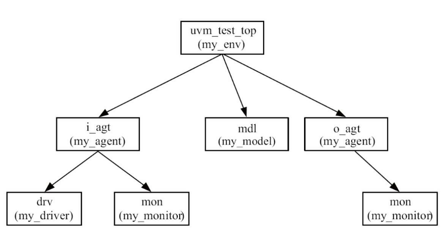
这里需要注意数据流动的方向,是从i_agt流动到mdl,而数据是i_agt中的my_monitor。因此在 my_monitor 需要定义一下:1
2
3
4
5
6
7
8
9
10
11
12
13
14uvm_analysis_port #(my_transaction) ap;
virtual function void build_phase(uvm_phase phase);
...
ap = new("ap", this);
endfunction
task my_monitor::main_phase(uvm_phase phase);
my_transaction tr;
while(1) begin
tr = new("tr");
collect_one_pkt(tr);
ap.write(tr);
end
endtask
uvm_analysis_port是一个参数化的类,其参数就是这个analysis_port需要传递的数据的类型,在本节中是my_transaction。到此,在my_monitor中需要为transaction通信准备的工作已经全部完成。
UVM的transaction级别通信的数据接收方式也有多种,其中一种就是使用uvm_blocking_get_port。该接收端已经在 my_monitor 中定义好了。可以往前去看my_monitor的代码。
在 my_monitor 和 my_model 中定义并实现了各自的端口之后,通信的功能并没有实现,还需要在 my_env 中使用 fifo 将两个端口联系在一起。下面是my_env 中的代码:1
2
3
4
5
6
7
8
9
10
11
12
13
14
15
16
17
18
19
20
21
22
23
24
25
26
27
28class my_env extends uvm_env;
uvm_tlm_analysis_fifo #(my_transaction) agt_mdl_fifo;
...
virtual function void build_phase(uvm_phase phase);
...
agt_mdl_fifo = new("agt_mdl_fifo", this);
endfunction
...
endclass
function void my_env::connect_phase(uvm_phase phase);
super.connect_phase(phase);
i_agt.ap.connect(agt_mdl_fifo.analysis_export);
mdl.port.connect(agt_mdl_fifo.blocking_get_export);
endfunction
`endif
```java
fifo的类型是uvm_tlm_analysis_fifo,其参数是存储在其中的transaction的类型。
>这里引入了connect_phase。它的执行顺序并不是从树根到树叶,而是从树叶到树根——先执行driver和 monitor的connect_phase,再执行agent的connect_phase,最后执行env的connect_phase。
但是该连接是与i_agt进行连接,怎么打通i_agt与my_monitor之间的通道呢?就是使用指针的方式。i_agt中的代码如下:
```java
uvm_analysis_port #(my_transaction) ap;
function void my_agent::connect_phase(uvm_phase phase);
super.connect_phase(phase);
ap = mon.ap;
endfunction
在这个代码里面没有实例化,直接将mon中的ap传给i_agt中的ap,就是用指针的形式,在访问i_agt中的ap时等价于访问mon中的ap。
六、scoreboard组件
该模块的作用就是比较DUT以及镜像模块的输出数值。代码如下:1
2
3
4
5
6
7
8
9
10
11
12
13
14
15
16
17
18
19
20
21
22
23
24
25
26
27
28
29
30
31
32
33
34
35
36
37
38
39
40
41
42
43
44
45
46
47
48
49
50
51
52
53
54
55
56
57
58`ifndef MY_SCOREBOARD__SV
`define MY_SCOREBOARD__SV
class my_scoreboard extends uvm_scoreboard;
my_transaction expect_queue[$];
uvm_blocking_get_port #(my_transaction) exp_port;
uvm_blocking_get_port #(my_transaction) act_port;
`uvm_component_utils(my_scoreboard)
extern function new(string name, uvm_component parent = null);
extern virtual function void build_phase(uvm_phase phase);
extern virtual task main_phase(uvm_phase phase);
endclass
function my_scoreboard::new(string name, uvm_component parent = null);
super.new(name, parent);
endfunction
function void my_scoreboard::build_phase(uvm_phase phase);
super.build_phase(phase);
exp_port = new("exp_port", this);
act_port = new("act_port", this);
endfunction
task my_scoreboard::main_phase(uvm_phase phase);
my_transaction get_expect, get_actual, tmp_tran;
bit result;
super.main_phase(phase);
fork
while (1) begin
exp_port.get(get_expect);
expect_queue.push_back(get_expect);
end
while (1) begin
act_port.get(get_actual);
if(expect_queue.size() > 0) begin
tmp_tran = expect_queue.pop_front();
result = get_actual.my_compare(tmp_tran);
if(result) begin
`uvm_info("my_scoreboard", "Compare SUCCESSFULLY", UVM_LOW);
end
else begin
`uvm_error("my_scoreboard", "Compare FAILED");
$display("the expect pkt is");
tmp_tran.my_print();
$display("the actual pkt is");
get_actual.my_print();
end
end
else begin
`uvm_error("my_scoreboard", "Received from DUT, while Expect Queue is empty");
$display("the unexpected pkt is");
get_actual.my_print();
end
end
join
endtask
`endif
my_scoreboard需要比较两种数据,前者通过exp_port获取,而后者通过 act_port获取。在main_phase中通过fork建立起了两个进程:
- 一个进程处理exp_port的数据,当收到数据后,把数据放入expect_queue中。
- 另外一个进程处理act_port的数据,这是DUT的输出数据,当收集到这些数据后,将参考数据从队列里面弹出,并调用my_transaction的my_compare函数。
最终的UVM树形图如下所示:
my_transaction的my_compare函数很简单,代码如下所示:1
2
3
4
5
6
7
8
9
10
11
12
13
14
15
16
17
18function bit my_compare(my_transaction tr);
bit result;
if(tr == null)
`uvm_fatal("my_transaction", "tr is null!!!!")
result = ((dmac == tr.dmac) &&
(smac == tr.smac) &&
(ether_type == tr.ether_type) &&
(crc == tr.crc));
if(pload.size() != tr.pload.size())
result = 0;
else
for(int i = 0; i < pload.size(); i++) begin
if(pload[i] != tr.pload[i])
result = 0;
end
return result;
endfunction
还有两个端口与外界的连接,在书里表示不在过多赘述,这里我简单说一下:首先有两个连接,一个是o_agt的数据,还有一个是my_model中的镜像数据,两者的输入接口都使用uvm_analysis_port #(my_transaction) ap;来定义。因此在本组件中uvm_blocking_get_port定义接受,连接代码如下:1
2
3
4
5
6
7
8
9
10
11
12
13 uvm_tlm_analysis_fifo #(my_transaction) agt_scb_fifo;
uvm_tlm_analysis_fifo #(my_transaction) agt_mdl_fifo;
uvm_tlm_analysis_fifo #(my_transaction) mdl_scb_fifo;
function void my_env::connect_phase(uvm_phase phase);
super.connect_phase(phase);
i_agt.ap.connect(agt_mdl_fifo.analysis_export);
mdl.port.connect(agt_mdl_fifo.blocking_get_export);
mdl.ap.connect(mdl_scb_fifo.analysis_export);
scb.exp_port.connect(mdl_scb_fifo.blocking_get_export);
o_agt.ap.connect(agt_scb_fifo.analysis_export);
scb.act_port.connect(agt_scb_fifo.blocking_get_export);
endfunction
七、field_automation机制
在my_transaction有三个函数,分别为my_print、my_copy以及my_compare函数。使用UVM中的field_automation机制可以将以上三个函数进行整合,该机制使用uvm_field系列宏实现:1
2
3
4
5
6
7`uvm_object_utils_begin(my_transaction)
`uvm_field_int(dmac, UVM_ALL_ON)
`uvm_field_int(smac, UVM_ALL_ON)
`uvm_field_int(ether_type, UVM_ALL_ON)
`uvm_field_array_int(pload, UVM_ALL_ON)
`uvm_field_int(crc, UVM_ALL_ON)
`uvm_object_utils_end
这里使用uvm_object_utils_begin和uvm_object_utils_end来实现my_transaction的factory注册,在这两个宏中间,使用uvm_field宏注册所有字段。通过这样的操作可以直接调用copy、compare、print等函数,而无需自己定义。
引入field_automation机制的另外一大好处是简化driver和monitor。my_driver的drv_one_pkt任务和 my_monitor的collect_one_pkt任务代码很长,其作用主要是将数据通过tran连接到DUT上。使用field_automation机制后,drv_one_pkt任务可以简化为:1
2
3
4
5
6
7
8
9
10
11
12
13
14
15
16
17task my_driver::drive_one_pkt(my_transaction tr);
byte unsigned data_q[];
int data_size;
data_size = tr.pack_bytes(data_q) / 8;
`uvm_info("my_driver", "begin to drive one pkt", UVM_LOW);
repeat(3) @(posedge vif.clk);
for ( int i = 0; i < data_size; i++ ) begin
@(posedge vif.clk);
vif.valid <= 1'b1;
vif.data <= data_q[i];
end
@(posedge vif.clk);
vif.valid <= 1'b0;
`uvm_info("my_driver", "end drive one pkt", UVM_LOW);
endtask
其中调用pack_bytes将tr中所有的字段变成byte流放入data_q中,减少了代码量。同理,在monitor中的解析也是这样:1
2
3
4
5
6
7
8
9
10
11
12
13
14
15
16
17
18
19
20
21
22
23
24
25
26task my_monitor::collect_one_pkt(my_transaction tr);
byte unsigned data_q[$];
byte unsigned data_array[];
logic [7:0] data;
logic valid = 0;
int data_size;
while(1) begin
@(posedge vif.clk);
if(vif.valid) break;
end
`uvm_info("my_monitor", "begin to collect one pkt", UVM_LOW);
while(vif.valid) begin
data_q.push_back(vif.data);
@(posedge vif.clk);
end
data_size = data_q.size();
data_array = new[data_size];
for ( int i = 0; i < data_size; i++ ) begin
data_array[i] = data_q[i];
end
tr.pload = new[data_size - 18]; //da sa, e_type, crc
data_size = tr.unpack_bytes(data_array) / 8;
`uvm_info("my_monitor", "end collect one pkt", UVM_LOW);
endtask
这里使用unpack_bytes函数将data_q中的byte流转换成tr中的各个字段。但是这里值得注意的是,unpack_bytes函数的输入参数必须是一个动态数组,所以需要先把收集到的数据放在data_q中的数据复制到一个动态数组中。==由于tr中的pload是一个动态数组,所以需要在调用 unpack_bytes 之前指定其大小,这样unpack_bytes函数才能正常工作(这里看不太懂)==。
七、sequence组件
sequence实际上就是一个产生激励的工具,在之前激励都是由my_dirver产生的,这次变为了sequence。在 一个规范化的UVM验证平台中,driver只负责驱动transaction,而不负责产生transaction。sequence机制有两大组成部分,一是 sequence,二是sequencer。
7.1 sequencer
下面是sequencer的代码部分:1
2
3
4
5
6
7
8class my_sequencer extends uvm_sequencer #(my_transaction);
function new(string name, uvm_component parent);
super.new(name, parent);
endfunction
`uvm_component_utils(my_sequencer)
endclass
可以看到,uvm_sequencer是一个参数化的类,其参数是my_transaction,即此sequencer产生的transaction的类型。但是,我们上文中的dirver其实也是参数化的类,应该在定义driver时指明此driver要驱动的transaction的类型:1
class my_driver extends uvm_driver#(my_transaction);
这样定义的好处是可以直接使用uvm_driver中的某些预先定义好的成员变量,如uvm_driver中有成员变量req,它的类型就是传递给uvm_driver的参数,在这里就是my_transaction,可以直接使用req:1
2
3
4
5
6
7
8
9
10
11
12
13
14task my_driver::main_phase(uvm_phase phase);
phase.raise_objection(this);
vif.data <= 8'b0;
vif.valid <= 1'b0;
while(!vif.rst_n)
@(posedge vif.clk);
for(int i = 0; i < 2; i++) begin
req = new("req");
assert(req.randomize() with {pload.size == 200;});
drive_one_pkt(req);
end
repeat(5) @(posedge vif.clk);
phase.drop_objection(this);
endtask
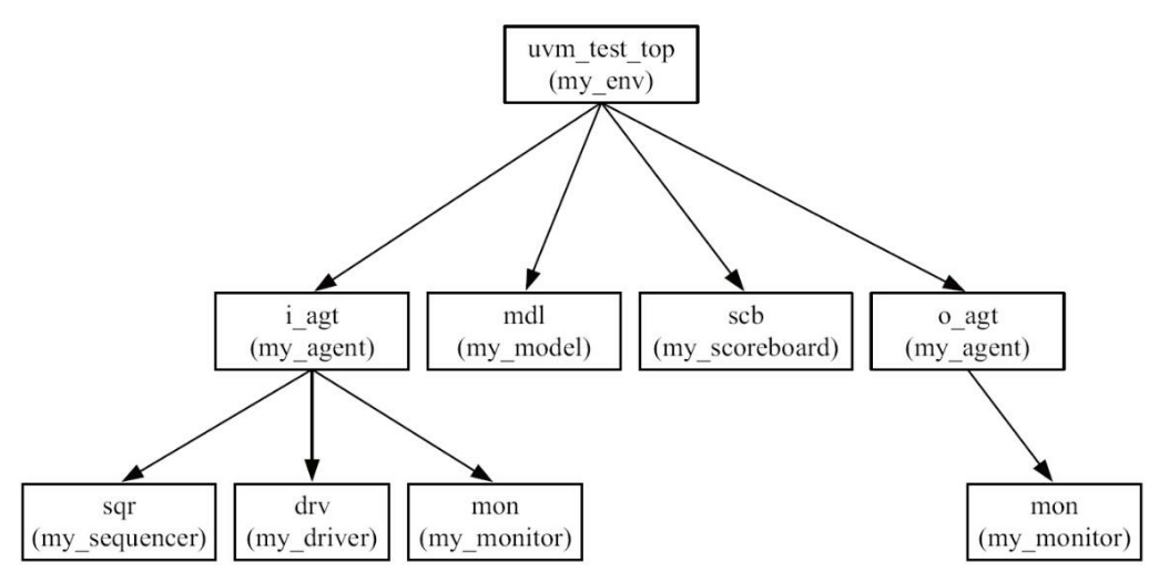
然后将该模块加入agent,得到的图如下所示:
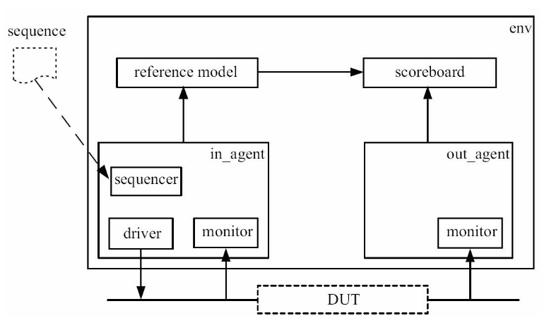
7.2 sequence机制
下面是前面提到的整个UVM的结构图,可以看见sequence的位置在比较偏的地方。这说明sequence并不是一个company而是一个object。
其代码如下:1
2
3
4
5
6
7
8
9
10
11
12
13class my_sequence extends uvm_sequence #(my_transaction);
my_transaction m_trans;
function new(string name= "my_sequence");
super.new(name);
endfunction
virtual task body();
repeat (10) begin
`uvm_do(m_trans)
end
#1000;
endtask
`uvm_object_utils(my_sequence)
endclass
可以看出,该模块在定义时同样要指定产生的transaction的类型,这里是my_transaction。每一个sequence都有一个body任务,当一个sequence启动之后,会自动执行body中的代码。
在上面的例子中,用到了uvm_do,其作用为:
- 创建一个my_transaction的实例m_trans
- 将其随机化
- 最终将其送给sequencer
下一步就是要将uvm_driver和uvm_sequencer以及uvm_sequencer和uvm_sequencer连接起来。
在uvm_driver中有成员变量seq_item_port,而在uvm_sequencer中有成员变量seq_item_export,这两者之间可以建立一个“通道”,通道中传递的transaction类型就是定义my_sequencer和my_driver时指定的transaction类型。因此在my_agent中, 使用connect函数把两者联系在一起:1
2
3
4
5
6
7function void my_agent::connect_phase(uvm_phase phase);
super.connect_phase(phase);
if (is_active == UVM_ACTIVE) begin
drv.seq_item_port.connect(sqr.seq_item_export);
end
ap = mon.ap;
endfunction
链接之后,dirver就可以向sequencer申请。代码如下:1
2
3
4
5
6
7
8
9
10
11task my_driver::main_phase(uvm_phase phase);
vif.data <= 8'b0;
vif.valid <= 1'b0;
while(!vif.rst_n)
@(posedge vif.clk);
while(1) begin
seq_item_port.get_next_item(req);
drive_one_pkt(req);
seq_item_port.item_done();
end
endtask
在如上的代码中,通过get_next_item任务来得到一个新的req,并且驱动它,驱动完成后调用item_done通知sequencer。这里为什么会有一个item_done呢,其主要作用就是让sequencer知道dirver已经接收到了这个req,形成一个类似于握手的机制。
uvm_do宏产生了一个transaction并交给sequencer,driver取走这个transaction后,uvm_do并不会立刻返回执行下一次的uvm_do宏,而是等待在那里,直到driver返回item_done信号。此时,uvm_do宏才算是执行完毕,返回后开始执行下一个uvm_do,并产生新的transaction。
然后就是最后一个问题就是将uvm_sequencer和uvm_sequencer连接起来,可以直接在UVM的根部进行定义:1
2
3
4
5
6
7task my_env::main_phase(uvm_phase phase);
my_sequence seq;
phase.raise_objection(this);
seq = my_sequence::type_id::create("seq");
seq.start(i_agt.sqr);
phase.drop_objection(this);
endtask
首先创建一个my_sequence的实例seq,之后调用start任务。start任务的参数是一个sequencer指针。
当然其实还有另一种方法来让dirver获得tran,就是使用try_next_item函数,上文中的get_next_item是阻塞的,而try_next_item则是非阻塞的,这样大大提高了代码的灵活性。1
2
3
4
5
6
7
8
9
10
11
12
13
14
15task my_driver::main_phase(uvm_phase phase);
vif.data <= 8'b0;
vif.valid <= 1'b0;
while(!vif.rst_n)
@(posedge vif.clk);
while(1) begin
seq_item_port.try_next_item(req);
if(req == null)
@(posedge vif.clk);
else begin
drive_one_pkt(req);
seq_item_port.item_done();
end
end
endtask
7.3 default_sequence机制
在刚才,sequence是在my_env的main_phase中手工启动的,但是在实际应用中, 使用最多的还是通过default_sequence的方式启动sequence。default_sequence的启动方式很简单,只需要在任意地方加入如下代码(以my_env举例):1
2
3
4uvm_config_db#(uvm_object_wrapper)::set(this,
"i_agt.sqr.main_phase",
"default_sequence",
my_sequence::type_id::get());
该代码同样使用了uvm_config_db,但是这里是在类里面调用的,第二个参数是相对于第一个参数的相对路径,由于上述代码是在my_env中,所以第二个参数中就不需 要uvm_test_top了。在top_tb中设置virtual interface时,由于top_tb不是一个类,无法使用this指针,所以设置set的第一个参数为null,并且第二个参数使用绝对路径uvm_test_top.xxx。
在第二个路径参数中,出现了main_phase。这是因为该代码是在这个位置的main_phase启动的。
至于set的第三个和第四个参数,书上说记住就行。
还有一个问题就是,在上一节启动sequence前后,分别提起和撤销objection,这里也需要加上这两个操作。sequencer在启动default_sequence时,会自动将自己传给sequence的starting_phase,因此可以这样写:1
2
3
4
5
6
7
8
9
10virtual task body();
if(starting_phase != null)
starting_phase.raise_objection(this);
repeat (10) begin
`uvm_do(m_trans)
end
#1000;
if(starting_phase != null)
starting_phase.drop_objection(this);
endtask
ok,结束。
八、bast_test组件
没想到吧,其实uvm的树根不是env,而是这个东西。该模块的代码如下:1
2
3
4
5
6
7
8
9
10
11
12
13
14
15
16
17
18
19
20
21
22
23
24
25
26
27
28
29
30
31
32
33
34
35
36
37
38class base_test extends uvm_test;
my_env env;
function new(string name = "base_test", uvm_component parent = null);
super.new(name,parent);
endfunction
extern virtual function void build_phase(uvm_phase phase);
extern virtual function void report_phase(uvm_phase phase);
`uvm_component_utils(base_test)
endclass
function void base_test::build_phase(uvm_phase phase);
super.build_phase(phase);
env = my_env::type_id::create("env", this);
uvm_config_db#(uvm_object_wrapper)::set(this,
"env.i_agt.sqr.main_phase",
"default_sequence",
my_sequence::type_id::get());
endfunction
function void base_test::report_phase(uvm_phase phase);
uvm_report_server server;
int err_num;
super.report_phase(phase);
server = get_report_server();
err_num = server.get_severity_count(UVM_ERROR);
if (err_num != 0) begin
$display("TEST CASE FAILED");
end
else begin
$display("TEST CASE PASSED");
end
endfunction
代码很常规,但需要注意的是,这里设置了default_sequence,其他地方就不需要再设置了。
上面的代码中出现了report_phase,在report_phase中根据UVM_ERROR的数量来打印不同的信息,其在main_phase结束之后执行。
除了上述操作外,还通常在base_test中做如下事情:
- 设置整个验证平台的超时退出时间;
- 通过config_db设置验证平台中某些参数的值。
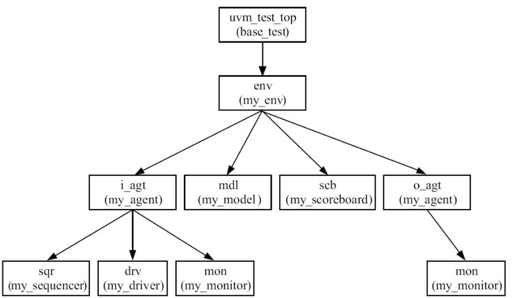
最终得到的树形结构如下所示:
九、总结
到现在为止,一个基本的UVM结构已经完全构建完毕了,后面我会继续为大家分享uvm的相关知识以及项目。谢谢大家支持!!!
 wechat